White paper 07 · Chapter 5
Water: in Kribi the design challenge is rain, not supply, and the goal is no process discharge
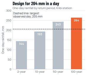
Kribi receives about 2,850 mm of rain a year, and a 100-year storm can drop 264 mm in a single day. Stormwater, not water supply, is therefore the main hydrological design driver. Process water demand is modest. Our planning estimates are about 0.6 million m³ a year for Phase 1 and about 2 million m³ at full capacity, assuming closed-loop cooling at about 2 m³ per tonne. Even the full-capacity figure is less than 1% of the Lobé’s median low flow. The real risks lie elsewhere: contaminated run-off from stockyards and slag areas, and oily water from casting and rolling, reaching small streams that have never been surveyed. Our objectives are closed-loop cooling, no discharge of process water in normal operation, and treated stormwater only. Every outfall will be monitored continuously, and the public will be able to see the results.
In this chapter (6)
5.1 How an EAF long-products works uses water
Water in an electric arc furnace (EAF) works is used mainly for cooling, and most of it can be recirculated. There are two kinds of circuit:
- Indirect cooling circuits carry heat away from the furnace’s water-cooled panels and roof, the ladle furnace, transformers, compressors and the oxygen plant. The water never touches the product, stays clean, and is recirculated through cooling towers or closed coolers.
- Direct-contact circuits spray water onto the hot billet in the continuous caster and onto the bar in the rolling mill. This water picks up mill scale (iron oxide flakes) and traces of lubricating oil. It needs settling in scale pits, oil skimming and filtration before it returns to the circuit.
Losses come from evaporation in cooling towers, from blowdown, which purges the circuit of dissolved salts, and from water used to cool slag and to suppress dust. Fresh water is needed only to replace those losses.
Benchmarks show how efficient this can be. The IFC EHS Guidelines give about 3 m³ per tonne for the EAF and 1 to 15 m³ per tonne for rolling, depending on recirculation [G03]. worldsteel’s 2024 averages, across all routes and all member plants, were a fresh-water withdrawal of 8.5 m³ per tonne of steel and a consumption of 2.3 m³ per tonne [T01]. Well-run EAF mills do better. The Malaysian EAF rebar works reviewed by the IFC in 2026 recycles about 8,000 m³ of water a day against 2,000 m³ of make-up, for 600,000 t a year of steelmaking capacity [T08]. On a 365-day basis that is about 1.2 m³ of fresh water per tonne.
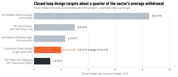
Source: worldsteel Sustainability Indicators 2025 [T01]; IFC EHS Guidelines for Integrated Steel Mills, Table 3 [G03]; IFC ESRS 51259, January 2026 (derived on 365 days) [T08]; Cameroon Steel planning basis [X03].
Our planning basis assumes about 2.0 m³ of fresh make-up per tonne of finished product, with a range of 1.5 to 3.0 m³ per tonne [X03]. This is an assumption to be refined by the design, not a measured value. It sits between the sector’s average consumption and the best EAF performance (Figure 5.1). The assessment will report the design water balance in detail. We will treat any upward revision as a matter to explain publicly.
5.2 How much water, and from where
Table 5.1 converts the planning basis into annual and daily volumes for each phase. It compares them with the low flows of the two coastal rivers. The comparison is for scale only. We do not plan to abstract from the Lobé, for reasons explained below.
Table 5.1 Indicative fresh-water demand by phase compared with river low flows
| Phase | Finished products (planned) | Fresh-water make-up | Average daily make-up | Share of the Lobé’s median low flow | Share of the Kienké’s 10-year low flow |
|---|---|---|---|---|---|
| Phase 1 | 0.3 Mtpa | About 0.6 million m³ a year | About 1,600 m³ a day | About 0.2% | About 0.4% |
| Phases 1 and 2 | 0.5 Mtpa | About 1.0 million m³ a year | About 2,700 m³ a day | About 0.4% | About 0.7% |
| Full design | 1.0 Mtpa | About 2.0 million m³ a year | About 5,500 m³ a day | About 0.8% | About 1.4% |
Source: Cameroon Steel planning model (2.0 m³ per tonne, 365 days) [X03]; Lobé median low flow 8.35 m³/s and Kienké 10-year low flow 4.68 m³/s [E01]. Derived values, rounded.
Three sources of supply are available, and we will rank them as follows.
First, the zone’s network. The port authority is building a dedicated water intake and treatment plant for the port platform, with production planned for early 2027 [K12]. A supply from the zone keeps abstraction under one managed authorisation and avoids a separate intake on a sensitive river. The public record does not say where that intake draws its water [K12]. If it draws on the Lobé, a commitment limited to our own intake would be met only on paper, so our commitment covers indirect abstraction too: no direct or indirect abstraction from the Lobé without a specific study. The source of the zone’s intake is listed as an evidence gap (Chapter 11).
Second, rainwater. Each hectare of roof in Kribi receives about 28,500 m³ of rain in an average year (2.85 m multiplied by 10,000 m²). The large halls of a melt shop and mills can therefore supply a meaningful share of make-up water, if collected and stored. Because there is no truly dry month (Chapter 1), storage requirements are moderate. We will size rainwater harvesting in the design and report its contribution.
Third, groundwater, but only after study. Boreholes supply the Kribi gas power plant [E15], so local aquifers can yield water. Nothing is known, however, about their depth, yield or quality near the site, or about how many village wells depend on them. Industrial abstraction needs prior authorisation after a 30-day public inquiry under the water law [L07]. We will not drill production boreholes until a hydrogeological study has identified safe yields and the protection of community wells.
We exclude direct abstraction from the Lobé, and indirect abstraction through a third-party supply unless a specific study shows it causes no harm. The river reaches the sea over the Chutes de la Lobé, a cultural landscape on Cameroon’s UNESCO Tentative List [B04]. Its estuary is a candidate habitat for the African manatee (Chapter 7). The volumes are small, but the symbolic and ecological weight of the river is not. A supply from the zone network or from rainwater avoids the question entirely.
5.3 Stormwater is the design driver
Rain in Kribi is heavy, frequent and intense. Annual totals are about 2,800 to 2,900 mm. The one-day rainfall expected once in two years is 144 mm. Once in ten years it is 193 mm, once in fifty years 243 mm and once in a hundred years 264 mm. The largest day observed at Kribi station in 33 years of record brought 205.3 mm [E01]. Reanalysis data badly underestimate these extremes: ERA5 gives a mean annual maximum of only 76 mm a day for the same area [E04]. Drainage must therefore be designed from station statistics, not from models.
Short-duration intensities are the missing piece. Gutters, pipes and channels must cope with the peak hour, not just the daily total, so drainage design needs intensity-duration-frequency curves. We found none published for Kribi. We will obtain pluviograph data from the national meteorological service and install an on-site tipping-bucket gauge at the start of the assessment (Chapter 11).
The plateau setting is an advantage. At about 40 to 100 m above sea level (rounded; to be confirmed by survey; Chapter 1), the platforms face no river or marine flood risk. The risks are local:
- flash flooding in valley bottoms;
- gullying of bare lateritic soil during earthworks;
- run-off that picks up dust, oil or metals from industrial surfaces.
Our drainage design follows four principles.
- Separate clean from dirty water. Rain on roofs and landscaped areas is clean and can be harvested or released. Rain on stockyards, slag areas, workshops and fuel stores is potentially contaminated and must be collected separately.
- Capture the first flush. The first part of a storm washes most pollutants off paved surfaces. Contaminated-area drainage will pass through retention basins sized to capture and treat it. The basins will have oil separators, sedimentation and pH correction where needed.
- Design for the 100-year storm. Retention basins and the main drainage network will be sized against the 100-year event. Overflows will be engineered so that, if they are ever exceeded, they release settled water rather than raw run-off.
- Control erosion before clearing. Lateritic soils erode quickly once their cover is removed. Sediment ponds and silt fences will be built before vegetation is cleared. Earthworks will be phased to keep bare areas small, especially before the September to October peak.
5.4 Effluents and the limits we will meet
In normal operation the works will produce three kinds of liquid effluent:
- blowdown from cooling circuits;
- treated water from the scale pits and filters of the direct-contact circuits;
- sanitary wastewater from canteens and washrooms.
Our objective is to reuse the first two inside the plant, for slag cooling, dust suppression and make-up to less demanding circuits. If that works, process water would leave the site only in exceptional circumstances. Sanitary wastewater will be treated in a package plant or, when available, in the zone’s wastewater treatment works. The port authority has tendered serviced land at Mboro that includes wastewater treatment [K13].
Where any water is discharged, Cameroonian law requires prior authorisation for effluents containing metals and monthly sampling by an approved laboratory [L05]. The IFC EHS Guidelines set the values in Table 5.2 for direct discharge to surface water [G03]. We will meet the IFC values at every outfall, or the national values if any are stricter.
Table 5.2 Effluent guideline values for direct discharge and Cameroon Steel objectives (selected parameters)
| Parameter | IFC EHS value (Integrated Steel Mills) | Cameroon Steel objective (planned) |
|---|---|---|
| pH | 6 to 9 | 6 to 9, continuous measurement |
| Total suspended solids | 35 mg/L | 35 mg/L; lower where the receiving stream is sensitive |
| Oil and grease | 10 mg/L | 10 mg/L |
| Chemical oxygen demand | 250 mg/L | 250 mg/L or lower |
| Zinc | 2 mg/L | 2 mg/L |
| Lead | 0.2 mg/L | 0.2 mg/L |
| Cadmium | 0.01 mg/L | 0.01 mg/L |
| Chromium total / hexavalent | 0.5 / 0.1 mg/L | 0.5 / 0.1 mg/L |
| Nickel | 0.5 mg/L | 0.5 mg/L |
| Iron | 5 mg/L | 5 mg/L |
| Mercury | 0.01 mg/L | 0.01 mg/L |
| Temperature increase | Below 3 °C at the edge of the mixing zone | Below 3 °C |
| Process-water discharge in normal operation | Not specified | None (reuse inside the plant) |
Source: IFC EHS Guidelines for Integrated Steel Mills, Table 2 [G03]; Décret 2011/2585/PM [L05]; Cameroon Steel objectives (planned).
5.5 Zero discharge: an aspiration we will test, not a slogan
"Zero liquid discharge" is often promised and less often delivered. Strictly, it means that no process water leaves the site and that all dissolved salts are recovered as solids, usually by evaporation. That takes energy, which in Kribi would come largely from the grid. We will therefore treat zero discharge as an aspiration to be reached in steps rather than a headline claim.
- Step 1 (design objective from Phase 1): no discharge of process water in normal operation. Cooling blowdown and treated direct-contact water are reused inside the plant. Only treated stormwater and treated sanitary wastewater are released.
- Step 2 (to be evaluated in the assessment): recovery of blowdown salts by membrane treatment and evaporation, so that even exceptional releases of process water stop. We will publish the energy and carbon cost of this step alongside its benefit.
- What zero discharge cannot mean: stormwater. In a climate with about 2,850 mm of rain a year, clean rain must leave the site, and treated run-off from industrial areas must be released after storage. The objective there is quality, not zero volume.
5.6 Protecting the receiving waters
The weakest point in today’s knowledge is the receiving environment. The small streams that drain the plateau have no flow or quality data. Neither does the Boussibelika stream that reaches the sea near the port, nor the Lobé tributaries to the east [E11]. Some of these coastal streams may hold restricted-range freshwater fishes (Chapter 7). We will therefore treat their protection as a design input:
- Survey before design is frozen. We will gauge and sample six to eight points in four campaigns over twelve months, covering both rainy and both drier seasons. The suite covers physico-chemistry, metals, hydrocarbons, microbiology and sediment, and we will survey fish and invertebrates (Chapter 11).
- Buffers. We will keep vegetated buffers of at least 30 m along watercourses and around wetlands, wider where the surveys justify it.
- No discharge to the Lobé basin without study. Any outfall will be located and designed on the basis of the stream surveys. No treated water will be released into the Lobé catchment unless a specific study shows it causes no harm.
- Groundwater watch. At least four monitoring piezometers, sampled quarterly, will detect any leakage from stores, basins or slag areas.
- Continuous outfall monitoring. Each outfall will have continuous pH, temperature and flow measurement and monthly laboratory analysis. Upstream and downstream sampling, and biological monitoring of invertebrates and fish, will show whether the stream itself is changing.
A fresh-water target of about 2 m³ per tonne, reported annually. Supply from the zone network and rainwater first, groundwater only after study, no direct or indirect abstraction from the Lobé without a specific study. Separate clean and contaminated drainage, with retention sized for the 100-year storm. No discharge of process water in normal operation. IFC effluent values at every outfall. Upstream and downstream monitoring of each receiving stream, published.
Sources cited in this chapter
Bracketed markers refer to these sources; the full list is in the annex. Full list of sources
- G03Environmental, Health, and Safety Guidelines for Integrated Steel Mills. IFC / World Bank Group, 30 Apr 2007.ifc.org/content/dam/ifc/doc/2000/2007-integrated-steel-mills-ehs-guide…
- T01Sustainability Indicators Report 2025 (2024 data). World Steel Association (worldsteel), Nov 2025 (updated Feb 2026).worldsteel.org/wider-sustainability/sustainability-indicators/
- T08Environmental and Social Review Summary 51259, Esteel Loan (EAF steel and rebar works, Malaysia). International Finance Corporation, 6 Jan 2026.disclosures.ifc.org/project-detail/ESRS/51259/esteel-loan
- X03Cameroon Steel reference configuration RC-1 (planning estimate): planned capacities, phases, indicative schedule and benchmark-based estimates, edition of 10 October 2026. Cameroon Steel, 10 Oct 2026.Cited by title and date
- E01Monographie du Nyong et des fleuves côtiers, tome 1 (J.-C. Olivry). ORSTOM (now IRD), Jul 1979.horizon.documentation.ird.fr/exl-doc/pleins_textes/divers11-03/01948.p…
- K12Énergie et infrastructures: un nouvel élan pour la compétitivité du Port de Kribi. Port Autonome de Kribi, 19 Aug 2026.Cited by title and date
- E15Environmental and Social Review Summary 25978, Kribi (gas-fired power plant). International Finance Corporation, 2010.disclosures.ifc.org/project-detail/ESRS/25978/kribi
- L07Loi n° 98/005 portant régime de l’eau; Décrets n° 2001/164/PM and 2001/165/PM. Presidency; Prime Minister (FAOLEX copies), 14 Apr 1998; 8 May 2001.faolex.fao.org/docs/pdf/cmr33974.pdf
- B04Le paysage culturel des chutes de la Lobé (Tentative List, ref. 6330). UNESCO World Heritage Centre, 2018.whc.unesco.org/fr/listesindicatives/6330/
- E04ERA5 hourly reanalysis (precipitation, wind, temperature), accessed through the Open-Meteo historical weather API. ECMWF; Open-Meteo.open-meteo.com/en/docs/historical-weather-api
- K13Le port de Kribi engage 3,5 milliards FCFA pour préparer l’arrivée de nouveaux industriels. Ecomatin, 11 May 2026.ecomatin.net/cameroun-le-port-de-kribi-engage-35-milliards-fcfa-pour-p…
- L05Décrets n° 2011/2582/PM (atmosphere), 2011/2583/PM (noise and odours), 2011/2584/PM (soils) and 2011/2585/PM (discharges). Prime Minister (FAOLEX copies), 23 Aug 2011.faolex.fao.org/docs/pdf/cmr195746.pdf
- E11OpenStreetMap data, Overpass API extract for the Kribi area (coastline, watercourses, roads, settlements, landuse, protected areas). OpenStreetMap contributors (ODbL), Base 24 Jul 2026; queried 10 Oct 2026.openstreetmap.org
Cite this chapter
Cameroon Steel (2026). Building responsibly in Kribi: a steelworks can meet international standards on four conditions. White paper 07, chapter 5: Water: in Kribi the design challenge is rain, not supply, and the goal is no process discharge. CS-WP-07. https://www.cameroon-steel.com/en/library/responsible-kribi/water/
Source