1/6≈ 1,100 °C
Reheat
The billet leaves the reheating furnace at an even temperature. Charging billets still hot from the caster saves much of the reheating energy.
Technology
The Kribi complex is designed around the electric route: an arc furnace melts scrap and reduced iron, a ladle furnace sets the grade, a continuous caster makes billets, and a mill rolls them into reinforcing bar and wire rod.
Charging
Sorted scrap and reduced iron go into the furnace by bucket; in Phase 1 the reduced iron is imported.
Steel
≈ 30 °C
typical temperature
IllustrativeRhythm
≈ 60min
from one heat to the next
AssumptionElectricity
0kWh/t
the charge is cold: about 1.21 t of scrap and reduced iron per tonne of product
DerivedElectricity so far
0 of 963
kWh per tonne of product
DerivedArc-furnace melting
Graphite electrodes strike arcs that melt the charge; oxygen and lime refine the bath and form the slag.
Steel
≈ 1,600 °C
typical temperature
IllustrativeRhythm
≈ 44min
of arc in a heat of 60 minutes
AssumptionElectricity
450kWh/t
of liquid steel, in a reference range of 347 to 500
AssumptionElectricity so far
479 of 963
kWh per tonne of product
DerivedLadle furnace
The metal is reheated, deoxidised and trimmed to the target grade; every heat is analysed by spectrometer.
Steel
≈ 1,600 °C
typical temperature
IllustrativeRhythm
≈ 20min
of heating per heat, to set the grade
AssumptionElectricity
37.5kWh/t
of liquid steel
AssumptionElectricity so far
519 of 963
kWh per tonne of product
DerivedContinuous casting
Steel solidifies in water-cooled moulds and leaves as square billets, cut to length.
Steel
≈ 1,000 °C
typical temperature
IllustrativeRhythm
≈ 40t/h
of liquid steel, cast without a stop
DerivedElectricity
32.5kWh/t
of liquid steel: caster, oxygen, water, compressed air
DerivedElectricity so far
553 of 963
kWh per tonne of product
DerivedReheating
Billets are brought to rolling temperature by induction, making the most of the heat left from casting.
Steel
≈ 1,100 °C
typical temperature
IllustrativeRhythm
≈ 37.5t/h
of product: the pace of the mill
DerivedElectricity
300kWh/t
of product, by induction (150 to 400, depending on how hot the billets arrive)
AssumptionElectricity so far
853 of 963
kWh per tonne of product
DerivedRolling
A train of stands reduces the section and lengthens the bar; the last grooves print the ribs.
Steel
≈ 1,050 °C
typical temperature
IllustrativeRhythm
≈ 37.5t/h
of product, 8,000 hours a year
DerivedElectricity
110kWh/t
of product, in a reference range of 70 to 140
SourcedElectricity so far
963 of 963
kWh per tonne of product
DerivedQuench and self-temper
A water quench hardens the skin of the bar, which the heat of the core then tempers: strength and ductility.
Steel
≈ 600 °C
typical temperature
IllustrativeRhythm
≈ 37.5t/h
of product: the bar crosses the water without stopping
DerivedElectricity
0kWh/t
water does the work; its pumps are counted with the auxiliaries
DerivedElectricity so far
963 of 963
kWh per tonne of product
DerivedCooling and testing
On the cooling bed, then cut to 12 m, tied in tagged bundles and tested in the laboratory.
Steel
≈ 30 °C
typical temperature
IllustrativeRhythm
12m
long: bars cut, bundled and tagged with their heat number
AssumptionElectricity
0kWh/t
the bar cools in air
DerivedElectricity so far
963 of 963
kWh per tonne of product
DerivedThe Kribi complex is designed around the electric route: an arc furnace melts scrap and reduced iron, a ladle furnace sets the grade, a continuous caster makes billets, and a mill rolls them into reinforcing bar and wire rod. Here is each step, why we chose it, and what it asks of the power grid and of quality control.
30.3%
Electric route share of world crude steel in 2025; 50% of capacity in development
Source
worldsteel, World Steel in Figures 2026; Global Energy Monitor, Pedal to the Metal 2026
worldsteel.org/data/world-steel-in-figures/world-steel-in-fi
450kWh/t
Arc-furnace electricity per tonne of liquid steel used in RC-1, within the 347 to 500 kWh/t reference range
Source
IFC, EHS Guidelines for Integrated Steel Mills (2007): EAF 1,250 to 1,800 MJ/t (347 to 500 kWh/t); 450 kWh/t is the RC-1 planning assumption within that range
~0.58t CO₂/t
Indicative intensity including upstream imported DRI: the closest basis to route averages. Scopes 1 and 2 alone: about 0.32 t in Phase 1 (0.33 t at full build-out)
Source
Cameroon Steel reference configuration RC-1: electricity per tonne (IFC ranges for the furnace and rolling; RC-1 assumptions for induction heating and auxiliaries) × Cameroon grid factor 226 gCO₂/kWh (Ember, 2024, when hydropower supplied about 72%; ARSEL reports about 90% for 2025: the 2024 factor is kept as the prudent value); direct emissions and upstream of imported DRI at 0.70 t CO₂ per tonne of DRI (gas-based shaft furnace) are RC-1 assumptions
~90%
Hydropower share of Cameroon’s electricity generation in 2025 according to ARSEL (about 72% in 2024 according to Ember, the year of the 226 gCO₂/kWh factor this site uses)
Source
ARSEL, Rapport d’activités 2025, 7 Sep 2026
arsel-cm.org/wp-content/uploads/2026/09/Rapport-ARSEL-2025.p
Step by step
Phase 1 starts at furnace charging. The first two steps, from ore to reduced iron, are the long-term option that would let the plant use Cameroonian ore.
Ore is concentrated, then agglomerated into iron-rich, low-silica pellets.
Natural gas strips the oxygen from the pellets without melting them, giving reduced iron.
Sorted scrap and reduced iron go into the furnace by bucket; in Phase 1 the reduced iron is imported.
Graphite electrodes strike arcs that melt the charge; oxygen and lime refine the bath and form the slag.
The metal is reheated, deoxidised and trimmed to the target grade; every heat is analysed by spectrometer.
Steel solidifies in water-cooled moulds and leaves as square billets, cut to length.
Billets are brought to rolling temperature by induction, making the most of the heat left from casting.
A train of stands reduces the section and lengthens the bar; the last grooves print the ribs.
A water quench hardens the skin of the bar, which the heat of the core then tempers: strength and ductility.
On the cooling bed, then cut to 12 m, tied in tagged bundles and tested in the laboratory.
The heart of the mill
The sequence follows the mill, stand by stand: each card takes over from the last, as each stand takes the bar the previous one left it.
1/6≈ 1,100 °C
The billet leaves the reheating furnace at an even temperature. Charging billets still hot from the caster saves much of the reheating energy.
2/6High-pressure water
High-pressure water jets crack off the oxide layer formed on the surface. This mill scale is collected and recycled.
3/6≈ 1,050 °C
The first stands reduce the section hard. The bar lengthens and speeds up at every pass.
4/6Alternating stands
Stands alternate between horizontal and vertical to keep the section round; engraved finishing rolls print the transverse and longitudinal ribs.
5/6Quench, then self-temper
A water box chills the skin of the bar; heat left in the core then tempers that layer. The result is a strong skin and a ductile core without costly alloying, which keeps the steel weldable.
6/6Ambient
The bar cools on the bed, is cut to length, bundled and tagged with its heat number, grade and standard. Samples go to the laboratory.
Typical temperatures, for illustration. Video sequence: visualisation.
Why the electric route
Three routes dominate world steelmaking. The blast furnace with an oxygen converter needs imported coke, plants of several million tonnes, and emits the most CO₂. Direct reduction followed by an electric furnace uses natural gas and very pure ore, and emits far less. The scrap-fed electric furnace emits least of all, but depends on scrap that Cameroon generates in limited quantities.
Cameroon Steel’s choice combines the last two: an electric furnace charged with scrap and, for about 30%, imported reduced iron, which guarantees the chemistry of the steel. On a hydro-dominated grid, indicative intensity would be about 0.58 t CO₂ per tonne including upstream imported reduced iron, the closest basis to route averages (Scopes 1 and 2 alone: about 0.32 t in Phase 1, 0.33 t at full build-out). When a direct-reduction-grade Cameroonian concentrate exists, the same furnace can take iron made from national ore.
151Mt
World direct-reduced iron output in 2025, 65% of it gas-based; sub-Saharan Africa makes almost none
Source
Midrex Technologies, 2025 World Direct Reduction Statistics, Sep 2026
www.midrex.com/world-dri-statistics/world-dri-production-rea
2.0m³/t
Closed-loop make-up water target, against a sector average consumption of 2.3 m³/t (2024)
Source
RC-1 objective (range 1.5 to 3.0 m³/t); worldsteel sustainability indicators 2025 for the sector average
| Route | Main inputs | CO₂, t/t | Typical size | For Kribi |
|---|---|---|---|---|
| Blast furnace and converter | Agglomerated ore, coking coal | 2.34 | Several Mt/yr | Unsuited: scale, imported coke, highest carbon exposure |
| Direct reduction and electric furnace | Direct-reduction-grade pellets, natural gas, electricity | 1.47 | Modules of 0.25 to 2.5 Mt/yr | Long-term option once ore and gas are secured |
| Scrap and electric furnace | Scrap, electricity | 0.69 | Mini-mills of 0.3 to 0.5 Mt/yr | In part: domestic scrap is limited |
| RC-1, Phase 1 (Kribi) | Scrap, 30% imported reduced iron, grid electricity | ≈ 0.58 * | 0.3 Mt/yr | Chosen first step |
Phased configuration
RC-1 reference configuration, indicative: front-end engineering will set the equipment, its sizes and its suppliers.
| Installation | Phase 1 | Phase 2 | Phase 3 | Option |
|---|---|---|---|---|
| Melting | One electric arc furnace and one ladle furnace | Second melt line | Melt-shop expansion | Direct-reduction module |
| Casting | Billet caster | Second caster | With the expansion | — |
| Reheating | Induction, hot charging | Gas-fired walking-beam furnace | Gas-fired walking-beam furnace | — |
| Rolling | Bar mill, high-speed wire-rod mill | Light and medium sections mill | Beam and heavy sections mill | — |
| Products | Rebar Ø8–32, wire rod Ø5.5–12 | Angles, channels, flats | H- and I-beams, heavy sections | Reduced iron for the furnace |
| Cumulative capacity | 0.3 Mt/yr | 0.5 Mt/yr | 1 Mt/yr | — |
| Average power | ≈ 36 MW | ≈ 53 MW | ≈ 94 MW | — |
PlannedIndicative Cameroon Steel, RC-1 reference configuration, 10 October 2026; power derived from IFC ranges for the furnace and rolling and RC-1 assumptions for induction heating and auxiliaries. No investment amount is published at this stage.
3D plant explorer
An electric long-products steelworks, like the one Cameroon Steel is planning at Kribi, moves material along a single line: scrap, melting, casting, rolling, dispatch. Pick a zone, or follow the steel from the light of the furnace to the grey of the finished bar.
Illustrative visualisation, not a design drawing
Everything starts here: scrap and other metallics arrive by truck, are inspected, weighed and graded. A silo holds direct-reduced iron (DRI/HBI), which supplements scrap when a steel grade calls for cleaner metal. The furnace charge is prepared here, basket by basket.
The electric arc furnace melts the charge with an arc struck between graphite electrodes and the metal; no ore or coke is needed. Liquid steel is tapped into a ladle and refined in the ladle furnace, which fine-tunes its temperature and chemistry before casting. This is the hottest stage of the plant and its largest user of electricity.
The ladle empties into a tundish that feeds water-cooled moulds, where the steel solidifies first at the surface and then through the core, as a continuous strand of square section. The strand is cut into billets, the semi-finished product that feeds the rolling mill. Casting continuously removes the ingot step and saves both energy and metal.
Billets are stored, inspected and marked so that every bar can be traced back to its heat. Before rolling, they pass through an induction heater that quickly brings them to rolling temperature, without a flame. Charging billets that are still hot from the caster substantially reduces the energy required.
A train of rolling stands stretches the glowing billet down to the required diameter and imprints the ribs of reinforcing bar. One line makes straight bars, the other wire rod in coils. Controlled cooling sets the mechanical properties, and on the cooling bed the steel turns from red to steel grey.
Bars are bundled, tagged and weighed, each lot with its inspection certificate. Trucks load under cover, cross the weighbridge and leave through the dispatch gate, bound for building sites and for the port. Keeping this traffic apart from scrap deliveries makes circulation smoother and safer.
Slag is the mineral layer that floats on molten steel and captures its impurities. Once cooled, it is crushed, and the metal it still contains is recovered and returned to the furnace. The resulting aggregate can be used in road works, subject to the required testing and approvals.
Furnaces, caster and rolling mill are cooled by water circulating in closed loops. Settling basins capture mill scale and particles, cooling towers reject the heat, and the water returns to the shops. Recirculating the water keeps withdrawals from local resources to what is strictly needed.
A plant of this kind connects to the high-voltage grid. The substation steps the voltage down for the arc furnace, the ladle furnace, the rolling mill and general services, and shields the public grid from the sudden load swings of the arc. Where this electricity comes from largely determines the carbon footprint of the steel.
The laboratory analyses every heat and tests bars in tension and bending, the basis of their certification. The training centre prepares operators, mechanics and electricians for steel trades, next to the offices and the health and safety services. The cluster sits by the main entrance, away from truck traffic.
A planted belt separates the plant from its neighbours. It softens noise and dust, screens the installations and carries stormwater drainage. Its species and width are for the environmental and social impact assessment to set, not for this illustration.
Power quality
The current of an arc furnace changes from one half-cycle to the next as scrap collapses into the arcs. The result is flicker (voltage fluctuations visible on nearby lighting), harmonics, phase imbalance and a heavy draw of reactive power. The average demand looks modest; it is the peak that sizes the connection.
We commit to treating these effects at source rather than exporting them to the grid: a dedicated 225 kV connection, a static VAR compensator or STATCOM with harmonic filters sized during front-end engineering, connection studies that meet the grid code and the transmission operator’s requirements, and melt scheduling coordinated with the system operator.
~36MW
Average power demand in Phase 1 (≈ 289 GWh/yr)
Source
Cameroon Steel, reference configuration RC-1 (edition 10 Oct 2026): capacities × electricity per tonne; arc furnace 450 kWh/t (IFC range 347 to 500) and rolling 110 kWh/t (IFC range 70 to 140), induction heating 300 kWh/t and auxiliaries 70 kWh/t (RC-1 assumptions); planning estimate, not a design figure
~55MVA
Maximum apparent power to request at the connection in Phase 1 (range 45 to 65 MVA): this, not the average, sizes the connection. The 15-minute average peak is about 47 MW
Source
RC-1 planning assumption: furnace and ladle-furnace transformers, mills, induction heating and auxiliaries with diversity
100 → 400MW
Kribi 225 kV line and substation capacity: 100 MW initially, 330 to 400 MW later
Source
Port Autonome de Kribi, communiqués of 6 Aug 2025 and 19 Aug 2026 (site visit by the Minister of Water and Energy)
Phase 1: 36.1 MW; Phases 1+2: 52.7 MW; 1 Mt/yr: 94.1 MW. Substation: 100 MW at first, then 330 to 400 MW. Connection demand, Phase 1 (≈ 55 MVA).
Phase 1’s average fits within the substation’s initial 100 MW; at full capacity the announced later capacity and a connection sized for peaks will be needed.
DerivedAssumptionSourced Averages: RC-1 (derived); maximum demand: RC-1 assumption (45 to 65 MVA); substation: Port Autonome de Kribi, 6 August 2025 and 19 August 2026.
Quality control
These are design objectives, not results: they will be verified by third parties before the first sales.
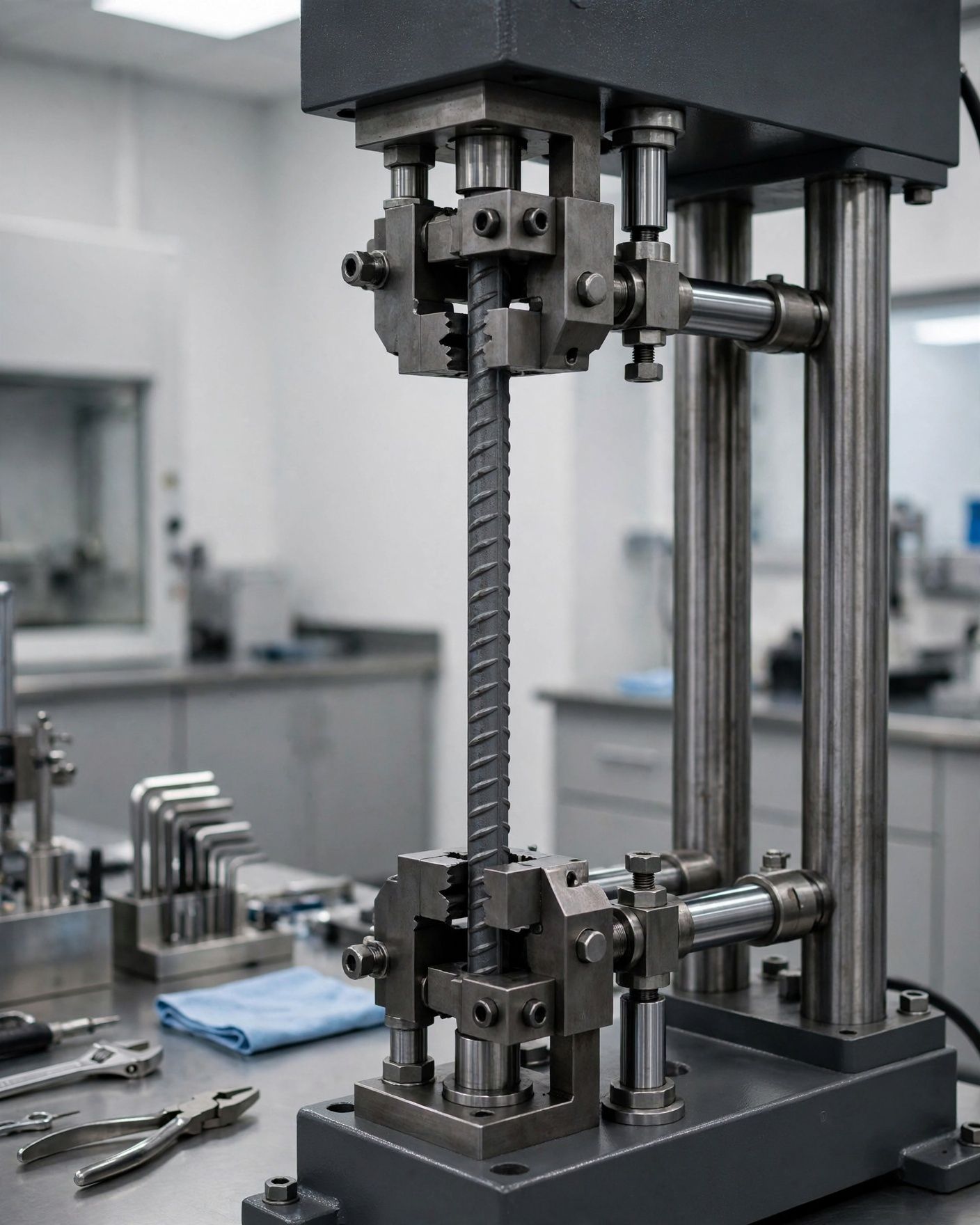
Spectrometer analysis at the ladle furnace and on the cast steel; carbon equivalent controlled to guarantee weldability.
Tensile (yield, tensile strength, Rm/Re ratio, elongation Agt), bend and rebend, at the frequency the standard requires.
Rib height and spacing and mass per metre measured on the line and in the laboratory.
Each bundle carries its heat number, grade, standard and diameter; inspection certificate type 3.1 (EN 10204).
Objectives: an ISO 9001 quality system, an ISO/IEC 17025 accredited laboratory, product certification by a third-party body.
Go further
White papers
Visualisation Covers: computer-generated images that do not depict an existing facility.