White paper 05 · Chapter 4
An arc furnace needs a strong connection and its own compensation, or it disturbs everyone else
An electric arc furnace draws power in rapid, irregular pulses that cause voltage flicker, harmonics and unbalance on the network. For a furnace of the RC-1 Phase 1 type, with a transformer of the 30 to 33 MVA class, a simplified screening suggests that the connection point needs a short-circuit power of roughly 2,000 to 7,000 MVA to stay within international flicker limits, depending on compensation. At the end of a radial branch such as Kribi, that means a direct high-voltage connection and dynamic compensation on site, sized from a measured study rather than assumed.
In this chapter (8)
- 4.1 An arc furnace is the most disturbing load a grid can host
- 4.2 The mills and induction heaters add a different kind of disturbance
- 4.3 The limits are set at the point where the plant meets the public network
- 4.4 A furnace of the 30 to 33 MVA class needs a 2,000 to 7,000 MVA connection
- 4.5 A 30 kV feeder would be too weak; a 225 kV bay is needed
- 4.6 Compensation removes most of the disturbance close to the furnace
- 4.7 A weak grid raises further issues beyond flicker
- 4.8 The steelworks and the grid operator should own the study together
4.1 An arc furnace is the most disturbing load a grid can host
An arc furnace melts steel by striking electric arcs between graphite electrodes and the metal charge. During the first minutes of each charge, the "bore-in" phase, the electrodes burn down into cold, irregular scrap. Pieces collapse, the arcs lengthen and shorten many times a second, and from time to time an electrode touches the charge and creates a momentary short circuit. Once a liquid pool forms, the arcs become more stable; during the final refining on a flat bath, the load is nearly steady. Then the power is switched off for tapping and recharging, and the cycle starts again.
Figure 4.1 illustrates that cycle for one heat of a furnace of the 40 t class with a transformer of the 30 to 33 MVA class, the classes planned for RC-1 Phase 1 [S07]. The figure is a constructed illustration rather than a measurement, but its shape is typical: two bore-in periods of violent fluctuation, two melting periods near the transformer’s limit, a steadier refining period and a power-off interval.
These fluctuations travel back into the network and cause four kinds of disturbance:
- Flicker. Rapid voltage fluctuations make lamps flicker. The human eye is most sensitive to fluctuations at around 8 to 10 per second, which is where arc furnaces emit strongly. Flicker is measured with a standard instrument and expressed as short-term severity (Pst, over 10 minutes) and long-term severity (Plt, over 2 hours); a value of 1.0 corresponds to the level at which flicker becomes irritating to many people [S13].
- Harmonics. The arc does not draw a clean sine-wave current. The distorted current creates voltage harmonics that overheat transformers and motors and disturb electronic equipment. Rectifiers for rolling-mill drives and induction heating add further harmonics of their own.
- Unbalance. The three phases of the furnace draw unequal currents, which unbalances the network voltage and heats rotating machines, including generators.
- Reactive power swings. The furnace circuit is highly inductive, so it draws large and fluctuating amounts of reactive power. Voltage falls when reactive demand rises, which lengthens melting time inside the plant and degrades supply for neighbours.
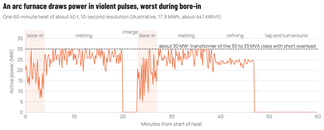
Source: Cameroon Steel illustration built from RC-1 planning values (furnace of the 40 t class, transformer of the 30 to 33 MVA class, 450 kWh/t) [S07].
The arc furnace is not the only large load in a steelworks. The ladle furnace behaves like a smaller arc furnace without the bore-in phase; induction heaters and mill drives are steady but harmonic-rich; oxygen plants and pumps are conventional motor loads. Figure 4.2 shows how these loads are typically arranged around one plant busbar, with the compensation equipment connected next to the furnace.
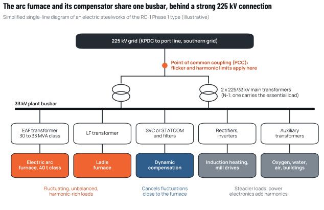
Source: Cameroon Steel, from RC-1 Phase 1 planning values (an EAF of the 40 t class with a transformer of the 30 to 33 MVA class, a ladle furnace, rectifier-fed mill drives and induction heating, a 225/33 kV main substation) [S07].
4.2 The mills and induction heaters add a different kind of disturbance
The arc furnace is the dominant source of flicker, but it is not the only source of disturbance in an electric steelworks. Rolling-mill motors are driven through power-electronic converters, and induction heaters are supplied through rectifiers and inverters. These loads are much steadier than the furnace, but they draw currents rich in characteristic harmonics. A six-pulse rectifier, for example, produces harmonics at orders 5, 7, 11 and 13 and so on (orders six times an integer, plus or minus one); twelve-pulse arrangements cancel the lowest of these. RC-1 Phase 1 includes rectifier-fed drives for its wire-rod line [S07], and induction heating for 300,000 t of billets a year would add a steady load of about 11 MW of power-electronic equipment (derived from the planning value of 300 kWh/t over 8,000 hours).
The furnace and the drives interact. The furnace emits a broad spectrum of harmonics, including even orders, during bore-in; the drives emit a narrow set of characteristic ones continuously. The filter banks of the furnace’s compensation system must therefore be designed together with the harmonic profile of the mills, and both must be checked against the network’s own resonances. This is why the connection study recommended at the end of this chapter covers the whole plant, not the furnace alone.
4.3 The limits are set at the point where the plant meets the public network
Power-quality limits apply at the point of common coupling (PCC), the point on the public network nearest to the plant at which other customers are, or could be, connected. The international reference for fluctuating loads connected at medium, high and extra-high voltage is the IEC technical report 61000-3-7, whose second edition (2008) sets out how a network operator should allocate flicker emission limits to individual installations so that the total stays within planning levels [S13]. For harmonics, the most widely used reference is IEEE Standard 519, last revised in 2022 [S73].
These references matter for two reasons. They define what the grid operator can require of a steelworks, and they define what the steelworks can demand of the network in return: a connection strong enough that reasonable compensation brings emissions within limits.
4.4 A furnace of the 30 to 33 MVA class needs a 2,000 to 7,000 MVA connection
The electrical stiffness of a network node is measured by its short-circuit power (Ssc), the power that would flow into a fault at that point. A stiff node, with high Ssc, barely notices a fluctuating load; a weak node amplifies it. To screen an arc furnace, this paper uses a simplified relation of its own, which takes the 99th-percentile short-term flicker as proportional to the ratio of two short-circuit powers:
Pst99 = Kst x SscF / SscPCC
where SscF is the short-circuit power of the furnace circuit (the power that flows when the electrodes are short-circuited on the charge, set by the furnace transformer, reactor and secondary circuit), SscPCC is the short-circuit power at the point of common coupling, and Kst is an empirical factor that reflects the type, weight and density of the scrap. According to the International Union for Electricity Applications (UIE), as cited in [S12], Kst lies between 48 and 85.
For RC-1 Phase 1, this paper assumes SscF at about twice the rating of a transformer of the 30 to 33 MVA class (assumed; the usual range is 1.5 to 2.5 times the rating), and gives the results to one significant figure. Figure 4.3 shows the resulting flicker estimate against the short-circuit power at the PCC.
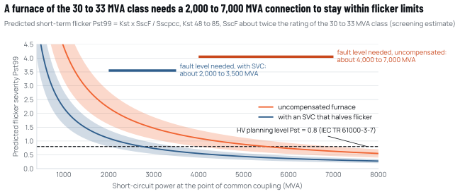
Source: simplified screening relation by Cameroon Steel (Annex A); Kst range according to the UIE, as cited in US Patent 10,145,612 (Siemens, 2018), which also notes that SVCs reduce generated flicker by approximately half [S12]; HV planning level from IEC TR 61000-3-7:2008 [S13]; furnace transformer class from RC-1 [S07]; SscF assumption by Cameroon Steel.
Two results follow (derived):
- Without compensation, keeping Pst99 below the HV planning level of 0.8 would require a short-circuit power at the PCC of about 4,000 to 7,000 MVA, more than a hundred times the furnace rating.
- With a static var compensator that halves flicker, as reported for SVCs in practice [S12], the requirement falls to about 2,000 to 3,500 MVA.
These are screening numbers, not design values: actual emission depends on the furnace’s charging practice, electrode control and secondary circuit, and the share of the planning level the network operator allocates to the plant may be well below 0.8. But they show the order of magnitude. A furnace of this size is a demanding load for any node that is not in the meshed core of a strong grid.
At full build-out, with two or three melt lines, the flicker from several furnaces would combine. With the cubic summation law, two identical furnaces would emit about 26% more flicker than one [S13], so the compensation and connection must be sized for the final configuration, not only for Phase 1.
4.5 A 30 kV feeder would be too weak; a 225 kV bay is needed
The fault level at Kribi’s 225 kV node has not been published and is the first number a connection study must establish (Chapter 11). What can be said now is that connecting the furnace through the port platform’s 225/30 kV substation would be the weakest option. A 30 kV busbar fed by three 60 MVA transformers would typically offer a short-circuit power of the order of 1,000 to 1,500 MVA, even with a stiff 225 kV source behind it (derived, assuming transformer impedances of 12% to 18%). That is below even the compensated requirement estimated above, and every other tenant on the same 30 kV network would share the disturbance.
The logical arrangement is a dedicated 225 kV bay at the port substation, a short 225 kV link to the steelworks and a 225/33 kV substation on site, with the furnace and its compensation on the plant’s own 33 kV busbar, as RC-1 provides for with its planned 225/33 kV substation [S07]. The PCC is then at 225 kV, where the fault level is highest and where the other users are furthest away electrically. Chapter 5 compares the connection options in detail.
4.6 Compensation removes most of the disturbance close to the furnace
Several measures reduce a furnace’s impact on the network. They are complementary rather than alternatives, and the right combination depends on the measured fault level and the share of the planning level allocated to the plant (Table 4.1).
Table 4.1 Measures that reduce the network impact of an arc furnace
| Measure | What it does | Effect on flicker | Effect on harmonics and power factor | Remarks |
|---|---|---|---|---|
| High-voltage connection (225 kV PCC) | Connects where the network is stiffest | Large: flicker scales inversely with fault level | Harmonic voltages also lower | Precondition at a weak node |
| Static var compensator (SVC): thyristor-controlled reactor plus filter banks | Absorbs the furnace’s reactive power swings within about a cycle | Roughly halves flicker [S12] | Filter banks correct power factor and absorb harmonics | Mature; large footprint |
| STATCOM (voltage-source converter) | Injects or absorbs reactive current electronically, faster than an SVC | Larger reduction than an SVC is claimed by suppliers | Can actively cancel some harmonics | Higher cost; smaller footprint |
| Passive harmonic filters alone | Tuned capacitor-reactor branches | Little or none | Correct power factor; absorb harmonics | Risk of resonance if not studied |
| Series reactor and electrode control | Stabilise the arc inside the furnace | Moderate, at source | Improves power factor in operation | Part of furnace design |
| Charging practice and scrap preparation | Denser, cleaner charge; continuous charging | Lower Kst, especially at bore-in | Indirect | Links to the metallic-charge strategy |
| Dedicated generation nearby | Fast-acting engines supply reactive power | Some support to voltage | Some support | Kribi gas plant engines are about 40 km away |
Source: US Patent 10,145,612 [S12]; IEC TR 61000-3-7 [S13]; EC ICIT, Consteel fact sheet [S38]; Cameroon Steel analysis.
For a plant of RC-1’s size at a node of uncertain strength, the prudent assumption is that dynamic compensation, SVC or STATCOM, will be required from Phase 1, with harmonic filters designed together with it, and that space and budget should be reserved for extending it when further melt lines are added. RC-1 reserves space for its 225/33 kV substation and reactive compensation, with room to extend both [S07].
4.7 A weak grid raises further issues beyond flicker
Flicker is the best-known problem, but a large fluctuating load on a modest system raises others that the connection study must address:
- Frequency and reserves. In Phase 1, the furnace would switch about 20 to 30 MW on and off roughly once an hour (Figure 9.2). On a system with a peak of 1,278 MW [S01], each step is about 2% of peak. The grid needs fast reserves to absorb these steps, and a sudden trip of the whole plant would remove up to about 50 MW at once. Hydro units and gas engines can provide such reserves, but the obligation must be planned and paid for.
- Resonance. Capacitor banks for power-factor correction can resonate with the network’s inductance at a harmonic frequency and amplify the very harmonics they are meant to absorb. A harmonic impedance study of the Kribi node is needed before filters are specified.
- Protection. Fault currents, relay settings and the coordination between the plant’s protection and SONATREL’s must be designed together, especially if the plant later adds on-site generation.
- Voltage stability. A heavily loaded radial line with a large inductive load at its end can suffer voltage collapse after a contingency. Reactive support at the load end is part of the answer.
4.8 The steelworks and the grid operator should own the study together
Cameroon already hosts an arc-furnace steelworks: Prometal’s melt shop in Douala, supplied at high voltage through a dedicated 50 MVA transformer under an access contract with SONATREL [S43][S42][S01]. Its power-quality arrangements are not in the public record, but its experience is the closest domestic precedent and should inform the grid code for fluctuating loads (Chapter 10).
For a new steelworks at Kribi, a power-quality programme would include five steps:
- Measure the network. Minimum and maximum fault levels at the Kribi 225 kV node under normal and contingency conditions, background flicker and harmonics, and a harmonic impedance scan.
- Allocate emission limits. The grid operator assigns the plant its share of the flicker and harmonic planning levels, following the IEC TR 61000-3-7 approach [S13].
- Design compensation against the allocation. Size the SVC or STATCOM and filters to meet the allocated limits for the final configuration, with guarantees measured at the PCC.
- Verify at commissioning. Measure emissions with the furnace at full production and adjust before acceptance.
- Monitor continuously. Install permanent power-quality meters at the PCC with data shared with the grid operator, so that problems are seen and solved jointly.
Sources cited in this chapter
Bracketed markers refer to these sources; the full list is in the annex. Full list of sources
- S07Cameroon Steel reference configuration RC-1 (planning estimate), edition 10 October 2026 (RC-1.1): phases, benchmarks with ranges, indicative balances and schedule. Cameroon Steel, 10 Oct 2026.Cited by title and date
- S13IEC TR 61000-3-7:2008, Electromagnetic compatibility, Part 3-7: Assessment of emission limits for the connection of fluctuating installations to MV, HV and EHV power systems (Ed. 2.0); indicative planning levels for flicker: Table 2 (section 4.2.1). International Electrotechnical Commission (table title read in the preview on the VDE Verlag site; values checked against secondary reproductions), 2008.vde-verlag.de/iec-normen/preview-pdf/info_iectr61000-3-7{ed2.0}en.pdf
- S73IEEE Std 519-2022, IEEE Standard for Harmonic Control in Electric Power Systems. IEEE, 2022.standards.ieee.org/ieee/519/10677/
- S71Regulatory texts listed on the regulator’s website: orders on the connection code and the market code (files could not be opened on the access date). ARSEL.arsel-cm.org
- S12US Patent 10,145,612: Flicker reduction in electric arc furnaces by means of flicker prediction from the state determination in the initial phase of the smelting process. Siemens (assignee now Siemens Energy Global), Granted 4 Dec 2018.patents.google.com/patent/US10145612
- S38Enhanced EAF steelmaking through continuous charging (Consteel). EC ICIT, n.d., accessed Oct 2026.innovation-centre-for-industrial-transformation.ec.europa.eu/innovativ…
- S01Rapport d’activités 2025 de l’ARSEL. ARSEL (electricity regulator), 7 Sep 2026.arsel-cm.org/wp-content/uploads/2026/09/Rapport-ARSEL-2025.pdf
- S43Matériaux de construction: l’offensive locale. Cameroon Tribune, 24 Apr 2023.cameroon-tribune.cm/article.html/56766/en.html/details_2
- S42Prometal, Acero Metal, Aciéries du Cameroun… qui est le plus gros consommateur d’électricité de la métallurgie camerounaise. EcoMatin, 15 Jul 2026.ecomatin.net/prometal-acero-metal-acieries-du-cameroun-qui-est-le-plus…
Cite this chapter
Cameroon Steel (2026). Cameroon’s hydro grid can power low-carbon steel if large users get firm supply, clear tariffs and gas. White paper 05, chapter 4: An arc furnace needs a strong connection and its own compensation, or it disturbs everyone else. CS-WP-05. https://www.cameroon-steel.com/en/library/energy-for-industry/power-quality/
Source