白皮书03 · 第5章 · 中文摘要
电弧炉炼钢车间:电力系统一并设计,一座40吨级电弧炉可支撑一期的大部分产量
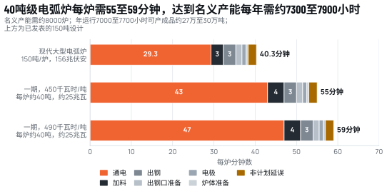
一座40吨级电弧炉,加上钢包精炼炉和一台钢坯连铸机,可支撑一期的大部分产量,但达到每年30万吨名义产能需要很高的可用率或更大的变压器。按RC-1规划值每吨钢水450千瓦时计,每炉约40吨,约需18兆瓦时,按约25兆瓦有功功率通电约43分钟,冶炼周期约55分钟;按上限规划值约490千瓦时(炉料中DRI或HBI占30%)计,冶炼周期约59分钟。名义产能所需的约8000炉将占用全年8760小时中的约7300至7900小时;按年运行7000至7700小时,可生产约27万至30万吨成品,与RC-1预计持续产量一致;否则需约36至40兆伏安的变压器(均为推算)[S03]。
本页为本章中文摘要;英文全文附于其后,可展开阅读。
炼钢车间最难的设计问题不是冶金问题,而是电气问题。电弧炉负荷大且波动快,会造成电压闪变和谐波;塞尔维亚Metalfer和美国夏洛特的钢筋厂都曾被迫加装STATCOM:前者实测闪变降低系数超过5,后者的设计指标同样高于5[S23, S24]。喀麦隆电网在2026年10月仍有150兆瓦工业需求未获满足[S89];克里比自治港(PAK)正在建设的225千伏线路初期可供100兆瓦,后期330至400兆瓦[S25, S34],一期约55兆伏安的最大需量在初期容量之内。DRI比例每增加10个百分点,电耗约增加14.5千瓦时/吨[S20]。
电价结构同样影响电弧炉的运行方式:喀麦隆10兆瓦以上用户没有公开的管制电价,六家高压用户通过双边合同供电[S51],因此容量电费和分时电价等条款应在关口1之前与接入协议一并商定。电弧炉可提供可调度负荷,即在一天之内把通电时段移出电网晚高峰,但不能提供持续的可中断负荷:一期产量已占用全年大部分时间,每中断一小时约损失一炉、即约40吨钢水,且无法补回(详见白皮书05)。
结论是:电弧炉、补偿装置和225千伏接入必须从一开始就作为一个系统来规定。
英文全文 15分钟 · 3450词The EAF melt shop: one furnace of the 40 t class can carry most of Phase 1 if the power system is designed with it
A single electric arc furnace of the 40 t class, with a ladle furnace and a billet caster, can carry most of Phase 1, but the full nameplate of 0.3 Mtpa needs high availability or a larger transformer. At the RC-1 planning value of 450 kWh per tonne of liquid steel, a heat of about 40 t takes about 55 minutes tap to tap; at about 490 kWh per tonne, the upper planning value with 30% DRI or HBI in the charge, about 59 minutes. Nameplate output, about 8,000 heats a year, then occupies about 7,300 to 7,900 of the 8,760 hours in a year, and at a realistic 7,000 to 7,700 operating hours the shop delivers about 270,000 to 300,000 t of finished products (all derived from the RC-1 planning basis) [S03]. The melt shop’s hardest design problem is not metallurgical but electrical. An arc furnace draws a large, rapidly fluctuating load that causes voltage flicker and harmonics, and Cameroon’s grid already leaves 150 MW of industrial demand unmet [S89]. The furnace, its compensator (an SVC or, preferably, a STATCOM) and the 225 kV connection must be specified as one system from the start.
5.1 A melt shop is a power system and a material line
Figure 5.1 shows the melt shop as two coupled chains. The material line runs from the scrap yard and the DRI or HBI silos through charging, the electric arc furnace, the ladle, the ladle furnace and the billet caster to the rolling mill. The power chain runs from the 225 kV supply through the plant substation and the compensator to the furnace and ladle-furnace transformers, the mills and the utilities. By-product streams leave the furnace as slag, fume and dust.
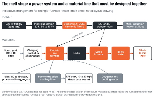
Source: Cameroon Steel. The slag range is the IFC benchmark for the solid residue of an electric arc furnace, which is mostly slag [S44]; the dust range is a planning range (the European reference document reports 10 to 30 kg) [S42].
RC-1, Cameroon Steel’s reference configuration, defines Phase 1 as one electric arc furnace of the 40 t class, a ladle furnace, a billet caster, an induction billet heater, a rebar mill and a high-speed wire-rod mill, with a nameplate capacity of about 300,000 t a year of finished products, or about 320,000 t of liquid steel, and an expected sustained output of 270,000 to 300,000 t of finished products [S03]. These are planning values; the supplier’s front-end engineering will set the equipment ratings.
5.2 Sizing the furnace from the tonnage
Furnace sizing starts from the tonnage the caster and mills need and works backwards. At nameplate, Phase 1 needs about 320,000 t of liquid steel a year [S03]. With heats of about 40 t, that is about 8,000 heats a year. The time per heat depends on how much energy each heat needs and how fast the transformer can deliver it. RC-1 plans on 450 kWh per tonne, a planning value within the IFC range of 347 to 500 kWh [S03, S44]. Read as an all-scrap figure, that value rises by about 14.5 kWh per tonne for each 10% of DRI in the charge [S20], which gives about 490 kWh per tonne with the planned 30% DRI or HBI. This paper therefore uses 450 kWh per tonne as the planning value and about 490 kWh as the upper planning value (Table 5.1).
A heat of about 40 t needs about 18 MWh at 450 kWh per tonne and about 19.6 MWh at 490 kWh. A furnace transformer in the 30 to 33 MVA class, operated at an average power factor of about 0.8, delivers about 25 MW of active power, so the power-on time is about 43 minutes in the first case and about 47 minutes in the second. Adding charging, tapping, tap-hole preparation, electrode handling, furnace preparation and an allowance for delays, about 12 minutes in all, gives a tap-to-tap time of about 55 and 59 minutes. About 8,000 such heats then occupy about 7,300 or 7,900 furnace hours, out of the 8,760 hours in a year (all derived; Annex A).
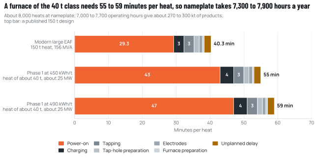
Source: indicative Phase 1 derived from the Cameroon Steel reference configuration RC-1 (planning estimate) [S03] and IFC energy benchmarks [S44]; benchmark design published by Badische Stahl-Engineering in La Metallurgia Italiana, June 2026 [S75].
Such utilisation is demanding for a first single-furnace shop on a grid that already leaves industrial demand unmet [S89]; a realistic planning range is 7,000 to 7,700 operating hours a year. In that range the furnace casts about 305,000 to 336,000 t of liquid steel at 450 kWh per tonne and about 285,000 to 313,000 t at 490 kWh. After casting and rolling losses, and within the mill’s nameplate, that gives about 270,000 to 300,000 t of finished products (derived; Annex A), which is the expected sustained output in RC-1 [S03]. One furnace can therefore carry most of Phase 1; reaching the full nameplate needs high availability, more chemical energy or a larger transformer. Delivering 320,000 t of liquid steel in 7,000 hours at 490 kWh per tonne would need a transformer of about 36 to 40 MVA (derived). The choice belongs in front-end engineering and in the supplier’s capacity guarantee, which Gate 1 requires (Chapter 10).
Either way, the utilisation explains two design priorities. First, power-on time dominates the cycle, so anything that shortens it (chemical energy from oxygen and carbon injection, burners, a well-foamed slag, scrap preheating or continuous charging) raises capacity directly. Second, the furnace has little spare time for unplanned stops, so maintenance planning, refractory practice and spare parts for transformers, electrodes and water-cooled panels are as important as nominal ratings.
The comparison in Figure 5.2 is instructive. A large modern furnace published in June 2026 combines a 150 t heat with a 156 MVA transformer, about 1.04 MVA per tonne, and achieves a net tap-to-tap time of 40.3 minutes with 29.3 minutes of power-on and a productivity of 224 t of liquid steel per hour [S75]. The Phase 1 furnace has a lower specific power, which lengthens the heat but also limits the disturbance it imposes on the grid. A US rebar mill in Charlotte, North Carolina, operates a 30 to 33 MVA furnace of the same transformer class, alongside an 18 MVA ladle furnace, on a 100 kV supply [S23].
Continuous charging is one proven way to raise output and lower energy use within the same transformer. The European Commission’s innovation centre reports that the Consteel process, which preheats scrap on a conveyor using furnace off-gas and feeds it continuously into a flat bath, reached 321 kWh per tonne at Pomina in Vietnam, cut electricity use by 10 to 15% and electrode use to below 1 kg per tonne [S90]. DRI and HBI are suited to continuous feeding through the roof, which stabilises the arc.
Table 5.1 Indicative Phase 1 melt-shop parameters (planning values, to be confirmed in front-end engineering)
| Parameter | Indicative value | Status | Basis |
|---|---|---|---|
| Finished products | Nameplate about 300,000 t/yr; expected sustained 270,000 to 300,000 t/yr | Planned; derived | RC-1 [S03]; Annex A |
| Liquid steel | About 320,000 t/yr at nameplate | Planned | RC-1 [S03] |
| Electric arc furnace | One furnace of the 40 t class | Indicative | RC-1 [S03] |
| Furnace transformer | 30 to 33 MVA class (about 25 MW active power) | Assumed | Annex A; class as in [S23] |
| Ladle furnace | One, matched to the furnace’s heats | Indicative | RC-1 [S03] |
| Heats per year; tap-to-tap | About 8,000 at nameplate; about 55 minutes (450 kWh/t) to 59 minutes (490 kWh/t) | Derived | Annex A |
| Furnace hours for about 8,000 heats | About 7,300 to 7,900, out of 8,760 in a year | Derived | Annex A |
| Operating hours for planning | 7,000 to 7,700 a year, giving 270,000 to 300,000 t/yr of finished products | Assumed; derived | Annex A |
| EAF electricity | 450 kWh/t liquid, planning value (IFC range 347 to 500); about 490 kWh/t, upper planning value with 30% DRI/HBI | Sourced; derived | [S03, S20, S44] |
| Electrodes | 2 to 6 kg/t (EU melt-shop range) | Benchmark | [S42] |
| Oxygen | 35 Nm³/t liquid (25 to 45) | Assumed | RC-1 [S03] |
| Metallic yield | 0.88 t liquid per t charged (0.85 to 0.91) | Assumed | RC-1 [S03] |
| Solid residue, mostly slag | 110 to 180 kg/t of product | Benchmark | IFC [S44] |
| EAF dust (managed as hazardous waste) | 10 to 20 kg/t liquid, a planning range (the European reference document reports 10 to 30) | Assumed | RC-1 [S03]; [S42] |
| Phase 1 maximum electrical demand | About 55 MVA (45 to 65) | Assumed | RC-1 [S03] |
Source: Cameroon Steel reference configuration RC-1 (planning estimate) [S03] and benchmarks as cited.
5.3 Energy and consumables depend on the charge
Electricity is the largest single input of the melt shop after iron units. EU melt shops use 404 to 748 kWh per tonne of liquid steel [S42]; the IFC benchmark is 347 to 500 kWh [S44]. The spread reflects furnace design, charge and practice. The share of DRI or HBI in the charge is one of the main drivers: the ENERGIRON reference indicates that each additional 10% of DRI raises EAF electricity by about 14.5 kWh per tonne, because the furnace must melt the gangue and finish reducing the residual iron oxide [S20]. Read against an all-scrap base of 450 kWh, a 30% DRI charge, the Phase 1 planning assumption, needs about 490 kWh per tonne, the upper planning value used in this paper, and a 70% domestic-DRI charge about 550 kWh (derived) (Figure 5.3).
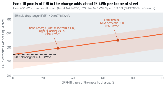
Source: Cameroon Steel, from the IFC range [S44], the ENERGIRON DRI penalty [S20] and the EU BREF range [S42]; Annex A.
Hot DRI changes the arithmetic. When a direct-reduction module sits next to the melt shop, DRI can be charged hot instead of cold, which recovers part of the energy spent in the shaft furnace and avoids the re-oxidation risk of storage. That is one reason for reserving the DR module’s site next to the melt shop rather than at the mine.
Graphite electrodes, refractories, lime and alloys complete the list of consumables. EU melt shops use 2 to 6 kg of electrodes per tonne [S42]; continuous-charging practice can bring that below 1 kg [S90]. Most of these consumables will be imported in Phase 1, and the supply chain for them belongs in the same procurement strategy as iron units (Chapter 3).
5.4 The ladle furnace and the caster set the rhythm of the shop
The ladle furnace decouples refining from melting. While the next heat melts in the EAF, the previous one is heated, alloyed, desulphurised and cleaned in the ladle. A ladle furnace typically raises temperature by about 4 °C per minute [S46], so a ladle furnace matched to heats of about 40 t has ample margin to hold steel at casting temperature and absorb small delays between the furnace and the caster. For rebar grades the ladle furnace adjusts manganese and silicon and, where needed, microalloying additions; for wire rod destined for drawing, it controls sulphur, oxygen and inclusions, which determine how well the rod draws into fine wire.
The billet caster must match the furnace’s output and run in long sequences, casting heat after heat without stopping, because each restart costs yield and time. Billet section is chosen with the mill: 150 mm square billets suit a 300,000 t/yr bar and rod mill, as in the mill ordered in Tanzania in September 2026 [S47]. Caster speed and strand count are then set so that the caster can absorb a heat in less than the furnace’s tap-to-tap time. Cast steel leaves a continuous caster at about 1,200 to 1,250 °C [S50], so billets sent straight to the mill keep much of that heat, which is the energy logic of Chapter 6.
5.5 Power quality: flicker, harmonics and reactive power
An arc furnace is one of the most disturbing loads a power system can carry. During melting, the arcs move, extinguish and restrike as scrap collapses, so the furnace’s reactive power swings within fractions of a second. Those swings cause voltage fluctuations that people perceive as flicker in lighting, and the arcs inject harmonic currents. Utilities set limits on both at the point where the plant connects. In the Serbian case described below, the limits at the grid owner’s substation were a short-term flicker severity (Pst, 95th percentile) below 1.0 and a long-term severity (Plt) below 0.75, with voltage unbalance below 1% and total harmonic distortion below 3% [S24].
The size of the disturbance depends on the ratio between the furnace’s power and the strength (short-circuit power) of the grid at the connection point. A strong grid absorbs the swings; a weak one transmits them to neighbouring consumers. Two published cases show what happens when the grid is not strong enough.
At Metalfer, a 400,000 t/yr scrap-based EAF mini-mill in Serbia that is the country’s only rebar producer, the furnace generated flicker that the existing conventional static var compensator (SVC) could not reduce enough; the transmission operator ordered the plant to solve the problem or have its power cut. A modular multilevel STATCOM rated from minus 49 to plus 121 Mvar at 20 kV, commissioned in March 2023, achieved a flicker reduction factor above 5 despite a relatively low short-circuit level [S24]. At Gerdau’s mill in Charlotte, USA, with a 30 to 33 MVA furnace, stricter flicker requirements followed the development of homes and businesses around the plant; the existing SVC was no longer sufficient, and an SVC Light (a STATCOM) of 0 to 64 Mvar was specified for a flicker reduction factor above 5; the supplier also expects productivity gains [S23].
Table 5.2 Power-quality limits and results at a 400 kt/yr EAF rebar mill after STATCOM compensation
| Indicator | Limit applied | Measured with STATCOM | Measured at |
|---|---|---|---|
| Power factor of the EAF load | 0.98 or higher | 0.999 | Customer substation |
| Short-term flicker, Pst (95%) | Below 1.0 | 0.653 | Grid owner’s substation |
| Long-term flicker, Plt (95%) | Below 0.75 | 0.569 | Grid owner’s substation |
| Voltage unbalance (95%) | Below 1% | 0.25% | Customer substation |
| Voltage total harmonic distortion (95%) | Below 3% | Below 0.7% | Customer substation |
Source: GE Vernova Power Conversion, case study of the Metalfer steel mill, Serbia, revised February 2024 [S24].
Both cases point to the same design rule for Kribi: assume that a fast compensator will be needed, specify it with the furnace, and verify it with a flicker study based on the actual short-circuit level at the plant’s connection point.
That connection point is still being built. Cameroon had 2,033 MW of installed capacity against a peak demand of 1,278 MW in 2025, but about 90% of its electricity came from hydropower [S51], and in October 2026 delays to the Nachtigal evacuation line left 150 MW of industrial demand unmet, with the 400 kV line then due in November 2026 [S89]. The Port Autonome de Kribi is building a 225 kV double-circuit line from the Kribi gas power plant to the port with a 225/30 kV substation, designed to deliver 100 MW at first and 330 to 400 MW at a later stage [S25, S34]. RC-1 estimates Phase 1 maximum demand at about 55 MVA [S03], which fits within the initial stage. Electricity is already a major cost for Cameroon’s steel industry: the largest consumer among Douala’s steel mills paid 8.37 billion FCFA for electricity in 2024 [S91]. A domestic precedent for a high-voltage solution exists: a Douala steel producer moved to a high-voltage connection with a dedicated 50 MVA transformer [S51]. White paper 05 (Chapters 2 and 3) analyses the power system and large-user supply in detail.
5.6 The electricity contract shapes how the furnace runs
How electricity is priced affects how a melt shop is operated, not only what it costs. Cameroon has no published regulated tariff above 10 MW: the country’s six high-voltage customers are supplied under bilateral contracts, and their average realised price in 2025 was about 18.4 FCFA per kWh, a legacy level (derived from the regulator’s report) [S51]. The highest published medium-voltage band, for loads of 9 to 10 MW, combines a monthly capacity charge per kW with a low energy charge, so that a customer who uses its contracted capacity for many hours pays less per kWh [S92]. The regulator’s cost-reflective average for 2025 was 105.46 FCFA per kWh, against 83.46 FCFA actually collected from medium and low-voltage customers [S93].
A large new contract is therefore likely to be negotiated, and its structure matters to the furnace. A capacity charge rewards a high, steady load factor, which a single furnace running about 7,300 to 7,900 hours a year provides. The same utilisation defines the flexibility the furnace can offer the grid. It offers schedulable load: within a day, the energy-management system described in Chapter 8 can shift power-on periods by minutes to hours, delay a heat or hold steel in the ladle furnace so that melting avoids the grid’s evening peak, which time-of-use pricing, if introduced, would reward. It does not offer interruptible load in any sustained sense. Phase 1’s tonnage already needs most of the hours in a year, so each hour of curtailment costs roughly one heat, about 40 t of liquid steel, that cannot be recovered later. Contract clauses should therefore reward scheduling around peaks rather than curtailment, and limit any emergency load-shedding to rare events that allow the heat in progress to be finished safely. These terms should be agreed alongside the connection agreement before Gate 1.
5.7 Safety and environment are designed in, not added
The melt shop’s main safety hazards are molten metal, water (which explodes on contact with liquid steel), oxygen and fuel gases, heavy lifting and high-voltage equipment. Fires and explosions are a recognised melt-shop hazard. International practice addresses these hazards through layout (separating water circuits from tapping and casting areas), water-leak detection in cooled panels, interlocks on oxygen lances, and training. The IFC’s EHS Guidelines for steel mills set the baseline expected by development lenders [S44].
On the environmental side, the furnace’s fume is captured by a direct off-gas system and a canopy hood and cleaned in a bag filter. EU best available techniques set a dust emission level below 5 mg/Nm³ for EAF fume treatment [S94]. The collected EAF dust, 10 to 20 kg per tonne of liquid steel (a planning range; the European reference document reports 10 to 30 kg) [S42], carries zinc, lead and cadmium from the scrap [S44] and has to be managed as hazardous waste: it must be stored securely and either treated or exported for zinc recovery. The furnace’s solid residue, mostly slag, amounts to 110 to 180 kg per tonne of product [S44]; the slag can be processed into aggregate for roads and concrete when its stability is verified. Water circulates in closed cooling loops: RC-1 assumes make-up of 1.5 to 3.0 m³ per tonne of product [S03], against a 2024 sector-average water consumption of 2.3 m³ per tonne reported by worldsteel [S01].
5.8 What the melt shop design means for decision-makers
Three conclusions follow. First, a single furnace of the RC-1 size can carry most of Phase 1, with an expected sustained output of 270,000 to 300,000 t of finished products; the full nameplate needs high availability or a larger transformer. That puts a premium on reliability, maintenance and supply of consumables, and makes the transformer rating a front-end engineering decision rather than a given. Second, the electrical design is a joint task of the steelworks, the transmission operator and the zone’s power infrastructure, and it must start before the furnace is ordered. Third, choices made now (continuous-charging capability, a compensator sized for future growth, space for a second furnace transformer and a direct-reduction module next to the shop) keep the later phases open at little extra cost.
Other sources cited in the English text
- S42Best Available Techniques Reference Document for Iron and Steel Production (EUR 25521). European Commission, Joint Research Centre, 2013.bureau-industrial-transformation.jrc.ec.europa.eu/sites/default/files/…
- S90Enhanced EAF steelmaking through continuous charging, scrap preheating (Consteel). European Commission, Innovation Centre for Industrial Transformation, Undated, accessed Oct 2026.innovation-centre-for-industrial-transformation.ec.europa.eu/innovativ…
- S46Siemens puts twin ladle furnace into operation for ArcelorMittal Bremen. AIST, Apr 2013.aist.org/siemens-puts-twin-ladle-furnace-into-operation-for-arcelormit…
- S47GSM Tanzania selects Danieli Technologies for new rebar and wire rod mill. SteelOrbis, 15 Sep 2026.steelorbis.com/steel-news/latest-news/gsm-tanzania-selects-danieli-tec…
- S50Hot charging of steel billets and slabs: impact on energy costs and emissions (S. W. Hesling). Steelonthenet, 1 Jan 2025.steelonthenet.com/insights/hot-charging.html
- S91Prometal, Acero Metal, Aciéries du Cameroun… qui est le plus gros consommateur d’électricité de la métallurgie camerounaise. EcoMatin, 15 Jul 2026.ecomatin.net/prometal-acero-metal-acieries-du-cameroun-qui-est-le-plus…
- S92Tableaux tarifaires, Décision ARSEL N°00000427 (tarifs moyenne tension 2023 à 2025). Agence de Régulation du Secteur de l’Électricité (ARSEL), Uploaded Jan 2026.arsel-cm.org/wp-content/uploads/2026/01/TABLEAUX-TARIFAIRES-decision-M…
- S93Décision fixant le montant du revenu maximum autorisé (RMA) d’ENEO au titre de l’exercice 2025 (réajustée). Agence de Régulation du Secteur de l’Électricité (ARSEL), 19 Dec 2025.arsel-cm.org/wp-content/uploads/2026/01/Decision-fixant-le-Montant-de-…
- S94Commission Implementing Decision 2012/135/EU establishing BAT conclusions for iron and steel production. EUR-Lex, 28 Feb 2012.eur-lex.europa.eu/legal-content/EN/TXT/HTML/?uri=CELEX:32012D0135
- S01Sustainability Indicators 2025 report (2024 data; route table added Feb 2026). worldsteel, Nov 2025, updated Feb 2026.worldsteel.org/wider-sustainability/sustainability-indicators/
本章引用的资料来源
方括号内的标记对应以下来源(按原文语言列出),完整列表见附录。 完整来源列表
- S23Gerdau plant in Charlotte, US: SVC Light for EAF flicker mitigation (customer story). Hitachi Energy,未注明日期,访问于2026年10月.hitachienergy.com/news-and-events/customer-stories/gerdau-plant-in-cha…
- S24Modular multilevel converter based STATCOM for electrical arc furnace application: Metalfer steel mill, Serbia (case study GEA34872). GE Vernova Power Conversion,修订:2024年2月20日.gevernova.com/power-conversion/sites/default/files/2024-02/GEA34872_Po…
- S89Nachtigal power line delays leave 150 MW of industrial demand unmet. Business in Cameroon,2026年10月9日.businessincameroon.com/public-management/0910-16939-nachtigal-power-li…
- S25Kribi franchit la ligne électrique 225 kV. Port Autonome de Kribi,2025年8月6日.按标题和日期引用
- S34Énergie et infrastructures: un nouvel élan pour la compétitivité du Port de Kribi. Port Autonome de Kribi,2026年8月19日.按标题和日期引用
- S20ENERGIRON technology: DRI-EAF production route using natural gas or H2. European Commission, Innovation Centre for Industrial Transformation,引用:2026年2月12日.innovation-centre-for-industrial-transformation.ec.europa.eu/innovativ…
- S51Rapport d’activités 2025. Agence de Régulation du Secteur de l’Électricité (ARSEL),2026年9月7日.arsel-cm.org/wp-content/uploads/2026/09/Rapport-ARSEL-2025.pdf
- S03Cameroon Steel reference configuration RC-1 (planning estimate): phases, benchmarks with ranges and indicative balances for the Kribi steelworks (Class 5), edition 10 October 2026, values as revised on that date. Cameroon Steel,2026年10月10日.按标题和日期引用
- S44Environmental, Health, and Safety Guidelines for Integrated Steel Mills. IFC, World Bank Group,2007年4月30日.ifc.org/content/dam/ifc/doc/2000/2007-integrated-steel-mills-ehs-guide…
- S75BSE-EAF: future-proof melting automated system for safe, reliable and efficient steelmaking (R. Schweikle, J. Apfel, A. Pezza), DOI 10.36146/2026_06_50. La Metallurgia Italiana (AIM),2026年6月.aimnet.it/la_metallurgia_italiana/2026/giugno/Aim_giugno2026_6.pdf
引用本章
Cameroon Steel(2026)。电炉炼钢是中部非洲的正确路线(中文摘要版)。白皮书03,第5章:电弧炉炼钢车间:电力系统一并设计,一座 40吨级 电弧炉可支撑一期的大部分产量。CS-WP-03。https://www.cameroon-steel.com/zh/library/technology-routes/eaf-melt-shop/
来源